The site of the project was a 100 m long, 15 m high corridor wall in an operating shopping centre, which had to be rebuilt to the desired unique façade design within the tightest possible timeframe.
Constructing a new building is a complicated enough process, but when it comes to transforming a building that is in daily use into an innovation, the task is even more difficult. A striking example of this was the redevelopment of the cinema wall in the Allee shopping centre, which was not the easiest project to carry out, not only from the construction point of view but also from the modelling point of view.
The site was a 100 m long, 15 m high corridor wall in the shopping centre, which had to be converted into the desired custom-made façade within the tightest possible timeframe. It was a challenging project: on the contractor’s side, the load-bearing structures were all concealed, the implementation and design plans were imprecise and the new structure itself was very unique. However, the most difficult task was to keep the construction time to a minimum, given the daily traffic on site. The only way to do this was to rely on accurate, flawless pre-design, so 3D technology seemed the obvious solution.
BEHIND THE SCENES AT THE ALLEE CINEMA WALL
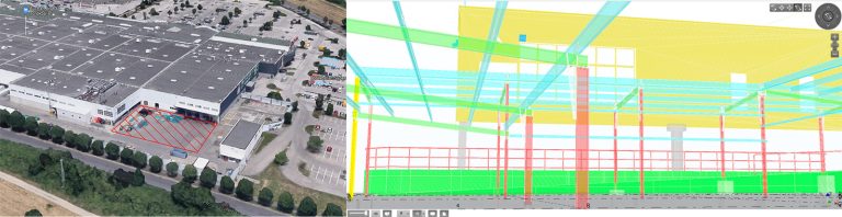
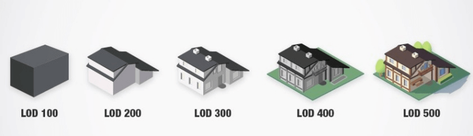
Laser scanning and the 3D model (background model) built from it were used to highlight the flaws in the resulting implementation and construction plans. The background model of the as-built model was used to correct for dimensional discrepancies and planar inaccuracies, while the 3D Site Viewer was used to make a visual comparison. A much more accurate background model was required for this project, where every millimetre counted, so we had to work with LOD500 accuracy instead of the usual LOD250-300, which is rare for our projects. As a comparison, here is an example that illustrates the different levels of detail in LOD (Level of Development):
During the modelling process, the contractor side started to collect new materials to be designed. Each sample received was installed on site and analysed to see how it fitted into the existing environment. To facilitate the final decision, several different types of perforated plates were produced in the background model, which was a time-consuming task to model at such a high LOD level. Once we had agreed with the designer on the chosen type, we could start integrating the manufacturer’s technical proposals and node solutions into the 3D model. The final 3D model helped us to guarantee the interconnection of the special structures in a slender, airy structure. This meant that the joint clearances had to be reduced to a minimum, which only became really feasible once the model was completed. This in turn made precision in construction a vital issue. Our 3D model was already georeferenced (positioned in a real coordinate system) thanks to the on-site laser scanning survey, so after making the necessary changes and after another round of design and manufacturer consultations, we could start the geodesics on site, which provided a solid basis for a professional construction. From this point on, our main task was to constantly monitor the quality of the finished structures, one by one, guaranteeing a perfect end result.
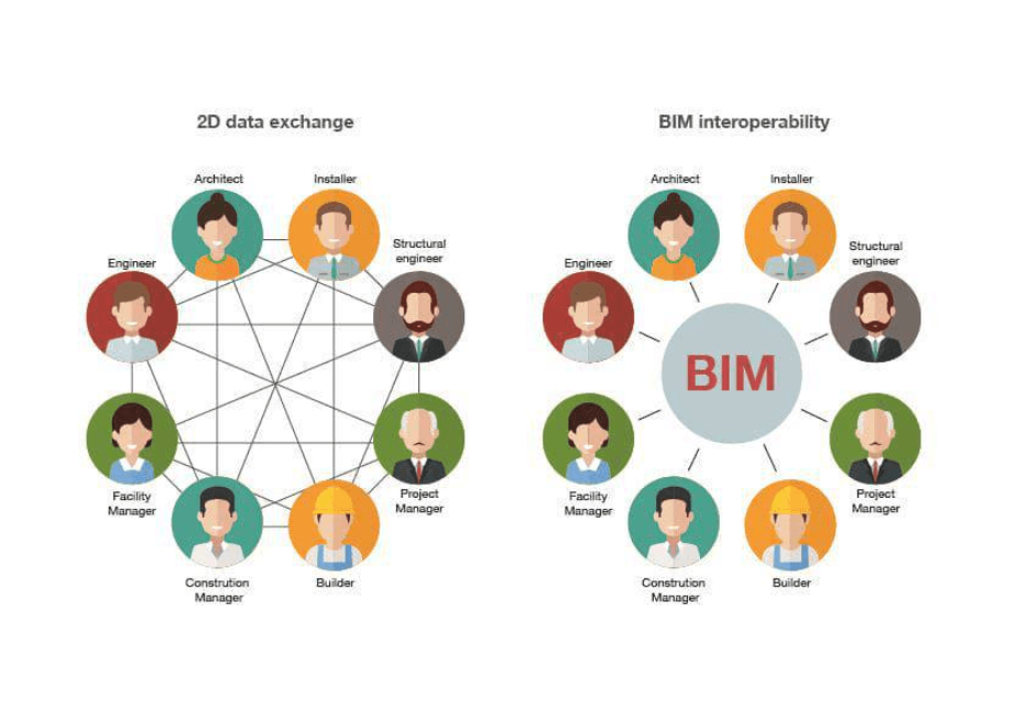
One of the major advantages of BIM is that it allows designers from different disciplines and different project participants to work simultaneously on the same model. That is, if you have an architect’s model, for example, the mechanical designer can use that as a background model, and the architect can use the mechanical model in the same way. At the same time, project managers, investors and contractors also prefer to use the building information model, whether for meetings or for producing marketing materials. This is possible because of the interoperability between BIM software. We talk about interoperability when the software can exchange information without losing data. In other words, there is a file format that can be extracted from one software and imported into another, so that the necessary information and data is still available.
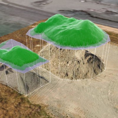
This interoperability is used for example in floor analyses when you need 3 software (Autodesk Revit, Trimble Realworks, Trimble Business Center) at the same time to get the desired result, or when you coordinate different trade models in the same Revit model. It is common to “pull in” engineering models designed by others into our own model in order to perform architectural redesigns without conflict.